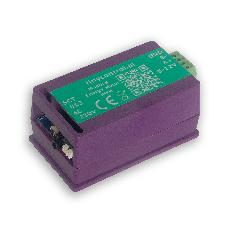
tMEM is a single-phase, bidirectional energy monitor with Modbus RTU interface.
By connecting this device to LK4, we gain an innovative solution for online electricity monitoring and setting events to optimize energy consumption in commercial, industrial and residential spaces. Thanks to its bidirectional operation, the meter can be used in measurements with photovoltaic installations.
The device is sold with a 100A/50mA CT (current transformer) with which it is calibrated to work.
tMEM is an energy monitor intended for data collection and automation in electrical installations. It does not have MIB certificates, which are characteristic of energy meters. Therefore, it cannot be used for energy billing.
Auto-save interval: 600 seconds
(Measurement data - such as energy readings - is saved to permanent memory at this interval.)
These defaults suit most standard installations. However, if you need to change the Modbus address, you can easily do so using the built-in button and status LED located next to the SCT 013 sensor connection socket.
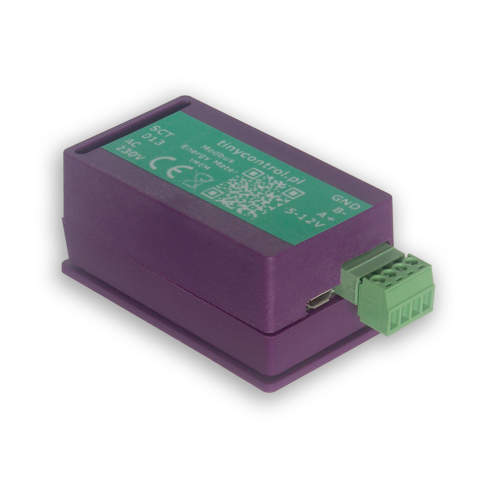
The tMEM integrates seamlessly with LK4 and LK3.5+ devices. It can be powered directly from the LK controller using its 5V and GND outputs. Then, connect it—either alone or together with other Modbus devices—to the LK’s Modbus A+ and B− terminals to establish communication.
Once connected, configure a custom Modbus module on the LK using the ready-to-use configuration preset available in the Downloads section. You can easily modify this preset to read only the parameters you need, such as voltage, current, power or energy values.
To update the firmware, the tMEM must be placed into bootloader mode. In this mode, the device appears as a mass storage device named RPI-RP2 when connected to a PC. Simply copy the new firmware file to that storage. After the upload, the device will automatically restart and resume normal operation with the new firmware.
You can enable bootloader mode in one of two ways:
Via USB Console
Connect the device to a PC and open the serial console (see instructions in Advanced configuration).
Then, send the command: bootloader.
The connection will be interrupted, and the device will restart in bootloader mode.
Via Hardware Button
Open the device casing to access the FLASH / SW1 button.
Press and hold this button before connecting the device to the PC via USB.
Keep holding it for a moment as the device powers on. Once it enters bootloader mode, you can release the button.
💡 Firmware files are available in the Downloads section.
To modify the settings, you will need to connect the tMEM to a computer via USB. The device can be powered through USB, so no additional power connections are necessary.
To establish a connection with the pulse counter, you'll need an application that can handle serial communication. Popular choices include:
PuTTy
TeraTerm
PySerial (Python library), which includes useful tools like pyserial-miniterm (for managing connections) and pyserial-ports (for listing available COM ports).
List Available Ports:
Run pyserial-ports to list the available COM ports before connecting the device. The output might look like:
COM1
COM3
COM15
COM16
COM17
Connect the Device
Plug in the tMEM and run the command again. The new COM port (e.g., COM11) will represent the connected device.
Connect to tMEM
Use the following connection parameters:
Baud rate: 115200
Byte size: 8 bits
Parity: None
Stop bits: 1
Example command:
pyserial-miniterm COM11 115200
Send Commands
Once connected, you can issue commands to the device. Each command must be followed by the Enter key. A useful command is ? or help, which provides a list of all available commands (described below).
Get the value of the auto-save function. This is the interval in seconds at which the counters are saved.
auto_save=X | as=X
Set the value of the auto-save function. Parameters: X - value in seconds, number <0, 65_535>, for 0 the function is disabled.
read_status | rs
Read the saved status.
write_status | ws
Write the status to Flash memory.
bootloader
Reboot the device into bootloader mode to update the firmware. When connected to a computer, it will appear as a storage device named RPI-RP2, to which you should copy the firmware file with the extension uf2. Then the device will reboot into normal operation mode.
restart
Restart the device.
verbose=X | v=X
Turn on or off verbose mode, which displays more messages.
help | ?
Display this help message with a list of available commands.
Some commands are useful only in special cases, which I present below.
Modbus addressing: When using multiple tMEM on one Modbus bus or with another device with a repeating address, it is worth using the address=X command to change it to a unique one.
To quickly change the Modus address, you can use the button (details here).
Automatic saving: If it is required to keep the status in the event of a power failure etc., the command auto_save=X should be used, resulting in their state being periodically saved to permanent memory. Be mindful of flash memory wear, as it has a limited number of writes (rated for 100k). Therefore, when using this feature you need to choose a value that is an acceptable compromise. The default value of 600 (seconds) should allow for about 2 years of operation.
The devices use a wear-leveling file system, which should increase the expected number of writes significantly (our test device performed over 440k writes without errors so far).
Resetting and setting energy status: Useful when replacing the energy monitor or changing the installation location. For example set_energy=123.123,0.345 will set positive energy status to 123.123 kWh and reverse energy to 0.345 kWh.
Saving changes: After changing settings using the commands: address=X, ratio_X=Y, auto_save=X, you must use save_config to save changes to permanent memory. Otherwise, they will be lost upon power loss or device restart.
Below is the list of Modbus registers available in the device.
The content corresponds to the output of the read_definitions command and includes register names, addresses, types, and divisors.